

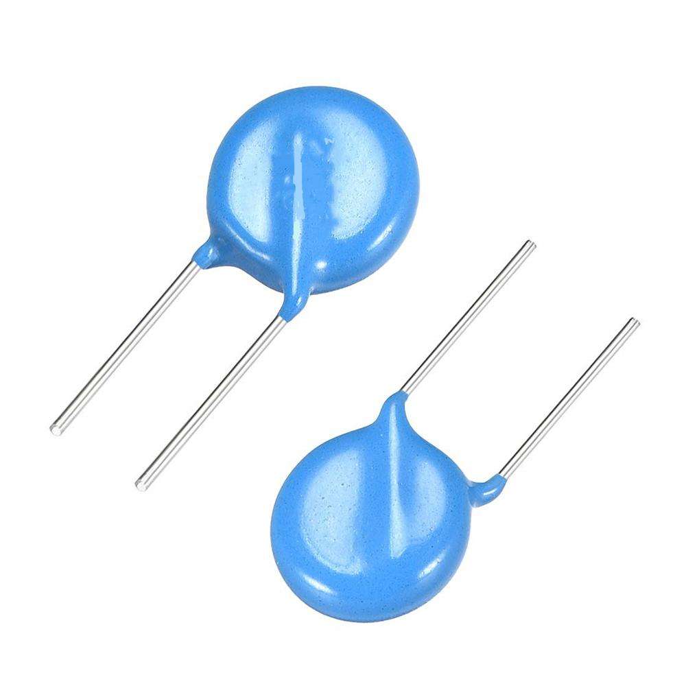

GDT gas discharge tube


|
Information of GDT The selection tips of GDT 1. The DC spark-over voltage of GDT should be more than 30% standard voltage and “high-end” tolerance, that protect the Max DC, continuous working voltage and circuits. 2.The IPP of GDT should be more than the surge current of transient circuit. |
|---|
| Part Number |
DC Spark-over Voltage @100V/S(V)
|
Max Impulse Spark-over Voltage @1KV/μs(V)
|
Max Surge Discharge Current @8/20μs 10times (KA)
|
Insulation Resistance @DC100V (GΩ)
|
Normal Alternating Discharge Current @50Hz (A)
|
Max Capacitance (1MHz) (pF)
|
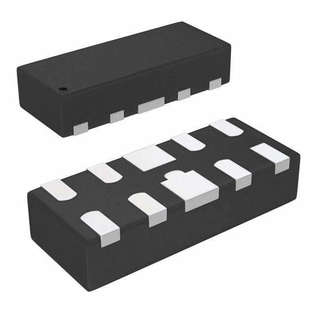
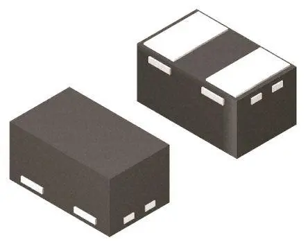
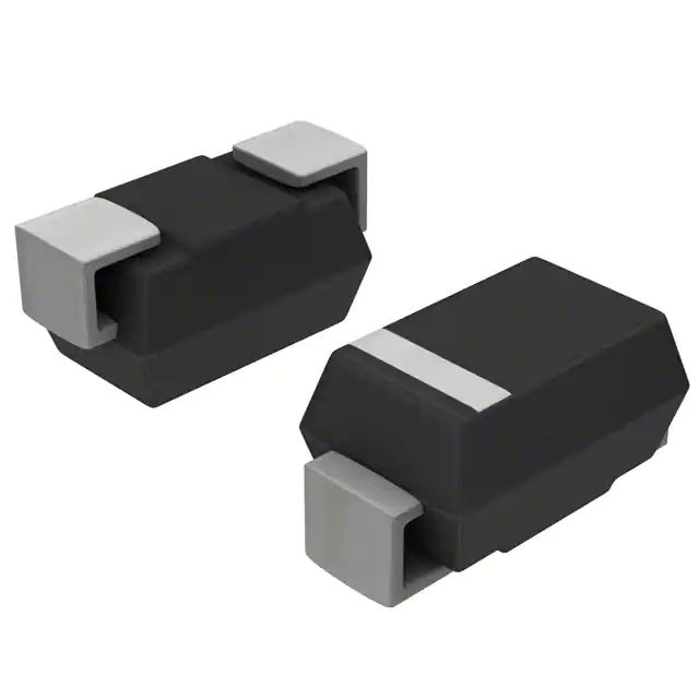
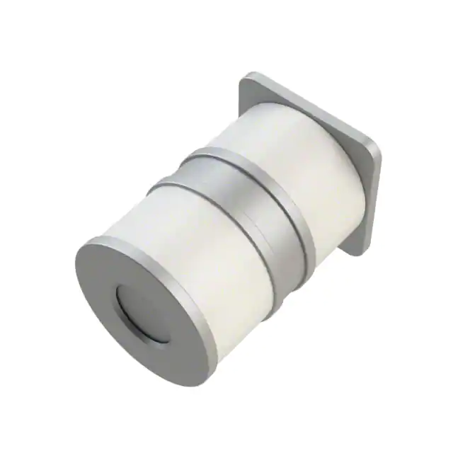
Package
|
Inner Diagram | Data sheet |
|---|---|---|---|---|---|---|---|---|---|
| 2R075SA-6 | 75±30 | 600 | 5 | 1 | 5 | 1 | 6.2*4 |
 |
|
| 2R090SA-6 | 90±30 | 600 | 5 | 1 | 5 | 1 | 6.2*4 |
 |
|
| 2R150SA-6 | 150±20 | 600 | 5 | 1 | 5 | 1 | 6.2*4 |
 |
|
| 2R230SA-6 | 230±20 | 700 | 5 | 1 | 5 | 1 | 6.2*4 |
 |
|
| 2R300SA-6 | 300±20 | 900 | 5 | 1 | 5 | 1 | 6.2*4 |
 |
|
| 2R350SA-6 | 350±20 | 950 | 5 | 1 | 5 | 1 | 6.2*4 |
 |
|
| 2R400SA-6 | 400±20 | 1000 | 5 | 1 | 5 | 1 | 6.2*4 |
 |
|
| 2R470SA-6 | 470±20 | 1100 | 5 | 1 | 5 | 1 | 6.2*4 |
 |
|
| 2R600SA-6 | 600±20 | 1300 | 5 | 1 | 5 | 1 | 6.2*4 |
 |
|
| 2R800SA-6 | 800±20 | 1500 | 5 | 1 | 5 | 1 | 6.2*4 |
 |
|
| 2R1000SA-6 | 1000±20 | 1900 | 5 | 1 | 5 | 1 | 6.2*4 |
 |
|
| 2R075TB-8 | 75±20% | <600 | 10 | 1 | 10 | 1.5 | 8*6 |
 |
|
| 2R090TB-8 | 90±20% | <600 | 10 | 1 | 10 | 1.5 | 8*6 |
 |
|
| 2R150TB-8 | 150±20% | <700 | 10 | 1 | 10 | 1.5 | 8*6 |
 |
|
| 2R230TB-8 | 230±20% | <800 | 10 | 1 | 10 | 1.5 | 8*6 |
 |
|
| 2R300TB-8 | 300±20% | <900 | 10 | 1 | 10 | 1.5 | 8*6 |
 |
|
| 2R350TB-8 | 350±20% | <1000 | 10 | 1 | 10 | 1.5 | 8*6 |
 |
|
| 2R400TB-8 | 400±20% | <1000 | 10 | 1 | 10 | 1.5 | 8*6 |
 |
|
| 2R420TB-8 | 420±20% | <1200 | 10 | 1 | 10 | 1.5 | 8*6 |
 |
|
| 2R470TB-8 | 470±20% | <1200 | 10 | 1 | 10 | 1.5 | 8*6 |
 |
|
| 2R600TB-8 | 600±20% | <1300 | 10 | 1 | 10 | 1.5 | 8*6 |
 |
|
| 2R800TB-8 | 800±20% | <1500 | 10 | 1 | 10 | 1.5 | 8*6 |
 |
|
| 2R075TD-8 | 75±20% | <600 | 20 | 1 | 20 | 1.5 | 8*6 |
 |
|
| 2R090TD-8 | 90±20% | <600 | 20 | 1 | 20 | 1.5 | 8*6 |
 |
|
| 2R150TD-8 | 150±20% | <700 | 20 | 1 | 20 | 1.5 | 8*6 |
 |
|
| 2R230TD-8 | 230±20% | <700 | 20 | 1 | 20 | 1.5 | 8*6 |
 |
|
| 2R300TD-8 | 300±20% | <800 | 20 | 1 | 20 | 1.5 | 8*6 |
 |
|
| 2R350TD-8 | 350±20% | <1000 | 20 | 1 | 20 | 1.5 | 8*6 |
 |
|
| 2R400TD-8 | 400±20% | <1000 | 20 | 1 | 20 | 1.5 | 8*6 |
 |
|
| 2R420TD-8 | 420±20% | <1200 | 20 | 1 | 20 | 1.5 | 8*6 |
 |
