

TSS Protection Thyristors


|
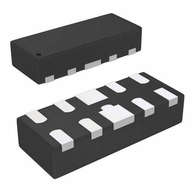
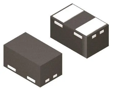
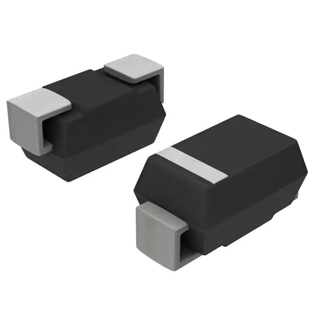
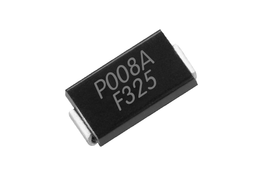
Information of TSS Thyristor Surge Suppressors, referred as TSS, TSS is based on the principle of SCR using ion implantation and production of a new type of protective device, with precise turn-on, rapid response (response time NS grade), surge absorption ability, bi-directional, high reliability characteristics. Due to its surge capacity is stronger more than same size TVS , and can be used instead TVS tube in passive circuits. They are small in size compared to their high surge current ratings. Operating voltages range from 20 Volts to 250 Volts with current ratings of 50 Amps to 200 Amps for a 10/1000µs waveform. Package configurations include axial lead, surface mount or cellular discs. The selection tips of TSS: 1. Vdm of TSS should be higher than the Max of the protected circuit DC or standard rated voltage working voltage, circuit and "high-end" allowances. If the Vdm is too low, the devices may enter an avalanche or much reverse current circuit to work properly. The serial should be connected the component voltage ,and the parallel to partial current; 2. VBO of the TSS must be less than the permitted circuit maximum instantaneous peak voltage. 3. The IPP of TSS should be higher than the transient surge circuit; Selecting the package according the PCB or preference. |
| Part Number |
Vdrm(V)
|
Idrm(μA)
|
Vs(V)
|
Ih(mA)
|
Is(mA)
|
It(A)
|
Vt(V)
|
Cj(pF)
|
Package
|
VBO(Min)V
|
VBO(MAX)V
|
VDRM (MIN)V
|
IDRM (MAX)uA
|
VTM(MAX)V
|
IT(MAX)A
|
IH(MAX)mA
|
Package
|
Inner Diagram | Data sheet |
|---|---|---|---|---|---|---|---|---|---|---|---|---|---|---|---|---|---|---|---|
| K2400L | 220 | 250 | 175 | 10 | 1.5 | 1 | 100 | DO-15 |
 |
||||||||||
| K2500L | 240 | 280 | 190 | 10 | 1.5 | 1 | 100 | DO-15 |
 |
||||||||||
| K3000L | 270 | 330 | 215 | 10 | 1.5 | 1 | 100 | DO-15 |
 |
||||||||||
| K3500L | 320 | 390 | 260 | 10 | 1.5 | 1 | 100 | DO-15 |
 |
||||||||||
| K4000L | 375 | 460 | 310 | 10 | 1.5 | 1 | 100 | DO-15 |
 |
||||||||||
| K4500L | 440 | 530 | 360 | 10 | 1.5 | 1 | 100 | DO-15 |
 |
||||||||||
| K5000L | 505 | 600 | 420 | 10 | 1.5 | 1 | 100 | DO-15 |
 |
||||||||||
| LM8S7N10 | 1 | SOP-8 |
 |
||||||||||||||||
| P0300SD | 25 | 5 | 40 | 50 | 800 | 2.2 | 4 | 100 | SMB |
 |
